adc-board-six-channels
adc-board-six-channels is a board containing six ADCs, intended for single-ended measurements. The boad supports ADCs with SOT-23-6 package and SPI interface.
A diagram of the board is shown in Fig. 10, where:
\(\text{V}_\text{CC}\) and \(\text{V}_\text{DD}\) are supply inputs. The ADCs can be supplied either with \(\text{V}_\text{CC}\) (typically 3V3) or \(\text{V}_\text{DD}\) (typically 5V). This depends on the specific ADC mounted on the board.
\(\text{A}_1, \dots, \text{A}_6\) are the analog inputs.
\(\bar{\text{CS}}\) and \(\text{CLK}\) are the chip select and clock signals. These two signals are shared among all ADCs on the board.
\(\text{SD}_1, \dots, \text{SD}_6\) are the data outputs of the ADCs.

Fig. 10 Diagram of the board.
Board and pinout
A fully populated board is shown in Fig. 11. The analog inputs are on the left (connector J1), while SPI interface is on the right (connector J2). The board’s pinout is shown in Fig. 12.

Fig. 11 Populated board.

Fig. 12 Pinout of the board.
ADC compatibility
The board supports any ADC having the footprint shown in Fig. 13. Example of compatible ADCs
TI’s ADC121S021 (12 bit, 50-200 ksps)
Analog Devices’ MAX11665 (12 bit, 500 ksps)

Fig. 13 ADC’s footprint.
Channel diagram
All channels are identifical, consisting essentially of a low-pass filter and an ADC. The circuit diagram is shown in Fig. 14. The cut-off frequency \(f_\text{c}\) of the filter is given by
The cut-off frequency can be adjusted according to the desired filtering requirements or sampling rate. Each channel can have a different cut-off frequency; however, all channels will have the same sampling rate since they share the chip select and clock signals.

Fig. 14 Circuit diagram of a single channel.
To help damping ringing in case of a longer cables on connector J2, a small resistor \(\text{R}_\text{d}\) is placed in series with the data output line of the ADC.
Supplying the board
As shown in Fig. 10, the ADCs can be powered either with \(\text{V}_\text{CC}\) (typically 3.3 V) or \(\text{V}_\text{DD}\) (typically 5 V). The voltage source is selected by populating the proper resistor on the PCB, as indicated in Fig. 15. Depending on which resistor is populated and which is not, the ADCs are powered as follows:
R15 populated, R16 not placed: ADCs are powered with 5 V (\(\text{V}_\text{DD}\))
R16 not placed, R15 populated: ADCs are powered with 3.3 V (\(\text{V}_\text{CC}\))
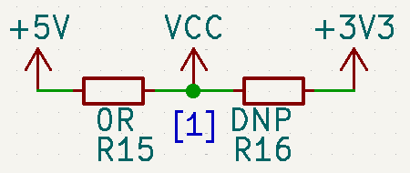
Fig. 15 Selecting the voltage source for the ADCs.
Note
\(\text{V}_\text{DD}\) and \(\text{V}_\text{CC}\) do not have to necessarily be 5 V and 3.3 V. You can choose if you want to power the ADCs with \(\text{V}_\text{DD}\) or \(\text{V}_\text{CC}\), as long as the chosen rail is within the voltage levels of the ADC chip.
Isolation
Isolated measurements are possible by combining the adc-board-six-channels board with the digital-isolator-2t6r isolator board. An example is shown Fig. 16.

Fig. 16 Isolated measurements by combining the adc-board-six-channels and digital-isolator-2t6r boards.
Signal preconditioning
If signal conditioning is required, it is possible to combine an ADC board with an amplifier board, see amplifier-board-six-channels. With the amplifier board, it is possible to amplify and offset analog voltage or current signals. It is also possible to use the board as an analog buffer. See amplifier-board-six-channels for more details.
Why six channels?
Originally, the board was intended to be used in three-phase systems, to sample three voltage and three current signals. That’s why the board was designed with six analog channels.
Application example
Fig. 17 shows one example where the adc-board-six-channels board was used. In the example, the ADC board was used to sample measurements from an experimental dc-dc converter, with sampling frequencies as high as 200 kHz, and SPI clock of 16.7 MHz. The board was populated with ADC121S021 chips, and all six ADCs were controlled simultaneously by an FPGA.

Fig. 17 ADC board put to use.
Fabrication files
To get the gerber files used to fabricate the ADC board, checkout commit 34480072c29c523887cbbbe66a5d34a5624f99fb, and find the files under adc-board-six-channels/gerber.